Zentec Motor
Choosing the right Torque Motor begins with the load, not the catalog cover. A motor that looks powerful may still overheat, vibrate, or respond poorly in your machine. Speed range, continuous torque, peak torque, duty cycle, and mounting space must work together. Measure the real load, including friction, acceleration, gravity, and unexpected resistance. A conveyor, robotic joint, and rotary table demand very different motor behavior.
Dr. R. Krishnan, a recognized authority on electric motor drives, states, “Motor selection must match the load, speed, and control requirements.” That principle remains practical on the factory floor. For example, a rotary table may need steady torque at low speed, while a robotic arm may require short bursts of high peak torque. Check thermal performance carefully. A motor can survive a brief overload, but repeated overloads shorten insulation life and reduce reliability. Cooling matters, too.
Do not chase maximum torque alone. Bigger is not always better. Excessive motor size can increase cost, inertia, and control difficulty. Review encoder resolution, drive compatibility, shaft stiffness, bearing capacity, and operating temperature. Ask how the motor behaves after thousands of cycles, not only during a ten-minute test. Even experienced engineers can underestimate cable heating or misread intermittent duty ratings. That is worth challenging. A reliable choice combines measured application data, manufacturer curves, and practical testing. The final Torque Motor should deliver controlled performance, acceptable heat, and enough reserve for real operating conditions.
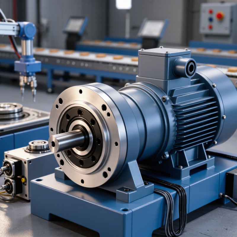
Choosing the right torque motor begins with defining its role in your application. The motor may provide continuous rotation, precise indexing, tension control, or direct load positioning. Each role creates different mechanical and electrical demands.
Describe the motion in practical terms. A rotary table may need rapid acceleration, quiet holding, and repeated stops. A winding system may require steady torque while its speed changes. Measure the load, operating speed, acceleration time, and duty cycle before selecting a motor.
Include friction, imbalance, and external forces. These details are often underestimated. They can increase required torque significantly.
Check whether the motor must hold position without movement. If so, review continuous torque, peak torque, and thermal limits separately. Continuous torque supports normal operation, while peak torque handles short acceleration events. A motor that meets the peak value may still overheat during repeated cycles. It happens more often than expected.
Also examine the load inertia and the motor’s feedback resolution. Poor matching can cause vibration, delayed settling, or unstable movement. In practical commissioning, temperature readings after several cycles reveal problems that calculations may miss.
Leave reasonable capacity for wear, changing loads, and imperfect assumptions. Oversizing is not always safer, because it may reduce responsiveness and increase energy use. Define the motor’s real task first, then compare its performance with the machine’s complete operating profile.
Choosing a torque motor starts with three practical numbers: required torque, operating speed, and duty cycle. Estimate load torque from the force and distance to the shaft. For example, a 12 N load acting 0.1 m from the center requires 1.2 N·m before friction is included. Add acceleration torque when the load must start quickly. A small safety margin helps, but excessive margin can increase cost and reduce control quality.
Measure the real load when possible. Friction is often higher than a calculation suggests. Use the relationship between linear speed and shaft radius to calculate rotational speed. A 0.1 m radius moving at 1 m/s needs about 95 rpm. Check both continuous and peak torque ratings. Peak torque may be available only for short periods.
Duty cycle determines thermal stress. Record how long the motor accelerates, runs, stops, and rests. For changing loads, calculate RMS torque across the complete motion cycle. A motor may meet peak torque but still overheat during frequent starts. This is easy to miss. In field testing, temperature should be checked near the motor housing and mounting surface. Do not rely only on catalog values. Actual inertia, friction, ambient temperature, and installation stiffness can change performance. Review the calculation after testing; the first estimate is rarely perfect.
Choosing a torque motor starts with the load, not the catalog. Measure continuous torque, peak torque, speed, acceleration, and duty cycle. A vertical axis also needs holding torque against gravity. Record friction, imbalance, and external shocks.
The International Energy Agency reports that electric motor systems consume about 53% of global electricity. This makes correct sizing an efficiency issue, not merely a performance choice. The U.S. Department of Energy also identifies motor-driven equipment as a major industrial electricity consumer. Oversizing may reduce thermal stress, but it can increase cost, inertia, and control difficulty. Undersizing creates heat quickly.
Match continuous torque to the RMS torque of the motion profile. Match peak torque to the hardest acceleration or disturbance. Check the motor’s rated speed against the required operating range. A motor delivering high torque at low speed may still fail when speed increases. Thermal limits matter. Consider ambient temperature, cooling, mounting orientation, and repeated starts. Real installations are less clean than spreadsheets.
In practice, I would test the heaviest product first. Leave a measured margin, not an arbitrary one. Ten percent may be insufficient for uncertain friction. Too much margin may hide a poor transmission design. Verify shaft stiffness, bearing loads, encoder resolution, and drive compatibility. IEC 60034-1 provides a useful framework for motor ratings, but application data remains decisive. That shortcut can fail. Recheck the calculation after a temperature-rise test.
| Selection Dimension | Required Application Data | Recommended Motor Specification | Typical Engineering Check | Selection Guidance |
|---|---|---|---|---|
| Continuous Torque | Torque required throughout the normal operating cycle, including friction and process resistance. | Continuous torque rating greater than the calculated RMS torque. | Use a design margin of approximately 20–30% where load conditions are well defined. | Ensure the motor can produce the required torque continuously without exceeding its thermal rating. |
| Peak Torque | Short-duration torque required for acceleration, deceleration, indexing, cutting, pressing, or disturbance rejection. | Peak torque rating higher than the maximum transient torque. | Verify the permitted peak duration, duty cycle, and peak-current limit of the drive. | Do not use peak torque as a continuous operating point; thermal and current limits still apply. |
| Speed Range | Minimum, normal, and maximum shaft speed required by the process. | Motor speed range covering the complete motion profile. | Check the torque available at the highest operating speed and the motor's rated speed. | Torque commonly decreases at higher speed because of back electromotive force and drive-voltage limits. |
| Acceleration | Target acceleration, deceleration, move time, and required positioning cycle. | Peak torque sufficient for inertial torque plus external load torque. | Tacc = Jtotal × α, where J is reflected inertia and α is angular acceleration. | Include rotor, fixture, tooling, workpiece, and any rotating transmission components in the inertia calculation. |
| Load Inertia | Mass moment of inertia of the rotor and all mechanically connected rotating parts. | Motor and drive combination compatible with the reflected load inertia. | For direct-drive systems, the load is not reduced by a gearbox ratio. | High inertia can increase settling time and following error; use motion-profile optimization or a larger motor when necessary. |
| RMS Torque | Torque values and duration for every segment of the operating cycle. | Continuous torque rating above the calculated cycle RMS torque. | TRMS = √[Σ(Ti2ti) / Σti]. | RMS torque is a practical way to evaluate heating during repeated acceleration, motion, dwell, and braking periods. |
| Positioning Accuracy | Required absolute accuracy, repeatability, resolution, and allowable angular error. | Feedback device and control resolution matched to the application. | Consider encoder resolution, mechanical compliance, bearing runout, thermal drift, and controller performance. | High-resolution feedback does not by itself guarantee accuracy if the structure or bearings are insufficiently rigid. |
| Direct-Drive Fit | Need for backlash-free motion, low maintenance, compact mechanics, and high stiffness. | Torque motor sized to deliver load torque directly at the axis. | Compare the motor's continuous and peak torque directly with the axis requirements. | Direct drive can eliminate gearbox backlash, but it may require a larger motor and careful cable and bearing design. |
| Thermal Conditions | Ambient temperature, enclosure, mounting orientation, cooling method, and duty cycle. | Thermal rating based on the actual installation, not only laboratory conditions. | Confirm whether the published rating assumes natural convection, forced air, or liquid cooling. | Restricted airflow, high ambient temperature, and enclosed mounting can reduce allowable continuous torque. |
| Drive Compatibility | Available DC bus voltage, continuous and peak current, feedback type, and control mode. | Motor electrical constants compatible with the servo drive. | Check phase current, voltage constant, torque constant, inductance, resistance, and commutation requirements. | The drive must support the motor's feedback technology and provide sufficient current at the required speed. |
| Mechanical Interface | Available envelope, shaft or rotor interface, mounting pattern, bearing arrangement, and axial/radial loads. | Motor dimensions and allowable loads compatible with the machine structure. | Verify bore or shaft size, mounting thickness, runout, concentricity, and bearing load capacity. | A frameless torque motor may require separate precision bearings; a housed motor may simplify installation. |
| Environmental Protection | Dust, coolant, oil, humidity, washdown, vibration, shock, and operating temperature. | Ingress protection and materials suitable for the installation environment. | Check the complete motor assembly, connectors, cable exits, and feedback device—not only the motor body. | Select appropriate sealing and corrosion protection for machine tools, robotics, clean areas, or outdoor equipment. |
| Regenerative Energy | Energy returned to the DC bus during rapid deceleration or overhauling loads. | Drive and braking system capable of handling regenerated energy. | Evaluate deceleration time, load inertia, maximum speed, bus capacitance, and braking-resistor requirements. | Excessive regeneration can cause drive overvoltage even when the motor torque rating is adequate. |
| Duty Cycle | Motion duration, dwell time, reversals per hour, cycle time, and operating hours per day. | Motor rating suitable for the complete thermal and mechanical duty cycle. | Use the full torque-speed-time profile rather than a single average torque value. | Frequent reversals can increase heating and mechanical stress even when average speed is low. |
| Final Validation | Worst-case load, production cycle, ambient conditions, and required service life. | Verified motor-drive-mechanics package with adequate safety margin. | Test acceleration, steady-state temperature, positioning performance, noise, vibration, and fault response. | Validate the complete system under the most demanding realistic operating condition before release to production. |
Selecting a torque motor begins with the machine’s real operating conditions, not only its rated torque. Record continuous torque, peak torque, speed, duty cycle, and ambient temperature. A motor running slowly may still generate substantial heat under constant load. Check the manufacturer’s thermal data carefully. Natural cooling may work in an open frame, but enclosed equipment often needs forced airflow or a larger housing.
Control performance deserves equal attention. Review feedback resolution, acceleration demands, settling time, and torque ripple. A high-resolution encoder can improve positioning, but it cannot correct poor tuning or mechanical backlash. Match the motor’s electrical characteristics with the drive and controller. Small mismatches can create noise, overshoot, or unexpected heating. Test the complete motion system when possible.
Installation details are easy to underestimate. Verify shaft alignment, bearing capacity, mounting stiffness, cable routing, and access for maintenance. A rigid mounting surface reduces vibration during rapid reversals. Keep power and feedback cables separated where practical. Leave enough space around the motor for heat release and inspection. I have seen otherwise suitable motors perform poorly because the mounting plate flexed. That mistake is costly.
Application data is rarely perfect. Recheck assumptions after the first test run. Measure the housing temperature, listen for resonance, and compare actual current with calculated values. Conservative sizing is useful, but excessive oversizing may reduce efficiency and control sensitivity. The best choice balances thermal margin, responsive control, and practical installation space.
How to Choose the Right Torque Motor for Your Application?
Comparing torque motor options requires more than matching a catalog torque value. In practical projects, I begin with the real duty cycle, not the ideal operating point. Record continuous torque, peak torque, speed, acceleration, load inertia, and operating time. A motor may meet peak torque yet overheat during repeated motion. Check the torque-speed curve carefully. Some options lose performance quickly near maximum speed.
Compare direct-drive and geared solutions against accuracy, backlash, efficiency, and maintenance needs. Frameless motors can save space, but they demand precise mechanical integration. Housed motors simplify installation, although they may increase mass and package size. Review cooling methods, bearing loads, feedback compatibility, cable routing, and environmental conditions. Small details matter.
Validation should use a weighted comparison table. Give clear scores for torque margin, thermal capacity, stiffness, cost, availability, and integration effort. Then test the preferred motor with the actual load, coupling, controller, and mounting structure. Measure temperature, position error, vibration, current, and settling time. Leave reasonable torque headroom. It protects against friction changes and imperfect assumptions. I have seen promising calculations fail because the fixture flexed under load. That mistake is easy to miss. Repeat the test at low and high temperatures when possible. Document every result, including failures, because an uncomfortable test result often reveals the most important design risk.
It can provide continuous rotation, precise indexing, tension control, or direct load positioning. Define the real task first.
Measure load torque, speed, acceleration time, inertia, duty cycle, friction, imbalance, and external forces. Include the heaviest product.
Continuous torque supports normal operation. Peak torque handles short acceleration events. A motor may meet peak demand yet overheat during repeated cycles.
Temperature readings after several cycles reveal problems that calculations may miss. Check ambient temperature, cooling, mounting direction, and operating time.Test it warm.
A vertical axis needs holding torque against gravity. Check whether the motor can hold position without movement during stops.
Poor inertia matching can cause vibration, delayed settling, or unstable movement. Review acceleration requirements and feedback resolution together.
No. Oversizing can increase cost, energy use, inertia, and control difficulty. Undersizing can create heat quickly.More capacity is not always better.
Compare accuracy, backlash, efficiency, maintenance, stiffness, and package size. A gear system may add backlash, while direct drive may demand stronger integration.
Test the actual motor with the real load, coupling, controller, and mounting structure. Measure temperature, current, vibration, position error, and settling time.The fixture may flex.
Score torque margin, thermal capacity, stiffness, cost, availability, and integration effort. Repeat tests at low and high temperatures when possible.Document failures too.
Choosing the right Torque Motor begins with clearly defining its role in the application, including whether it will provide direct drive, continuous rotation, precise positioning, or high holding torque. Start by calculating the load’s required torque, operating speed, acceleration, and duty cycle. Consider peak and continuous demands, as well as any variations in the working process, to avoid selecting a motor that is either underpowered or unnecessarily large.
Next, compare the motor’s rated torque, speed range, feedback options, and control compatibility with the mechanical load and motion profile. Thermal performance is equally important, especially in compact installations or continuous-duty applications. Review cooling conditions, mounting space, shaft alignment, cabling, and maintenance access before making a final decision. Comparing several suitable options and validating the selection through calculations, simulations, or practical testing can help confirm reliable performance, efficient operation, and long-term system stability.