(1) Frequency setting
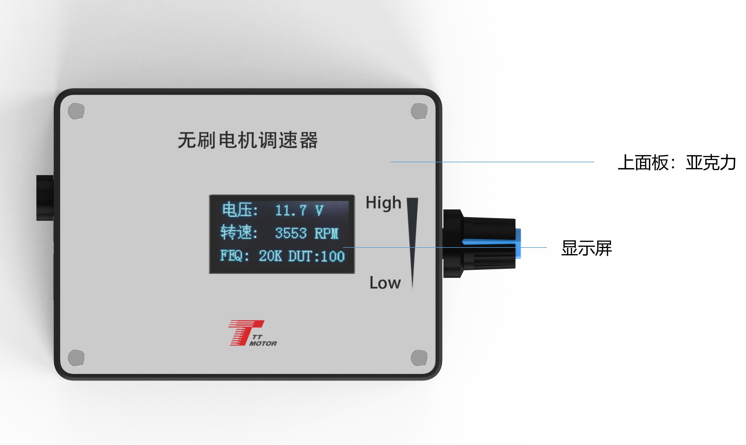
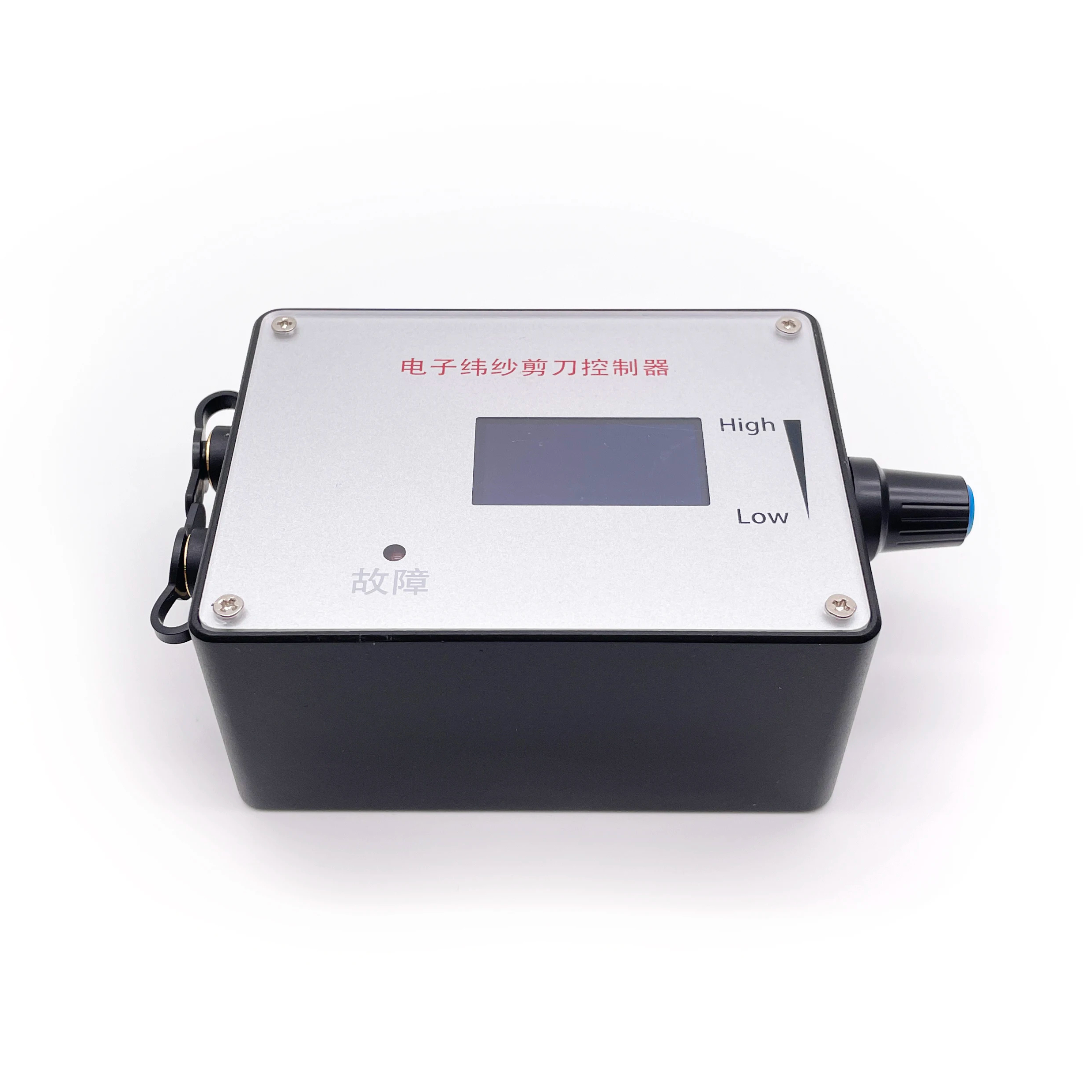
Before power-on, press and hold touch switch 1. Turn on the power and wait until the screen displays "FEQ:20K", then release the button. Touch switch 1 to decrease, and touch switch 2 to increase. The factory default is 20KHz.
(2) Number of poles setting
Before power-on, press and hold both touch switch 1 and touch switch 2. Turn on the power and wait until the screen shows "number of poles: 1 polarity", then release the buttons. Touch switch 1 to decrease, and touch switch 2 to increase. The factory default is 1 pole.
(3) Feedback setting
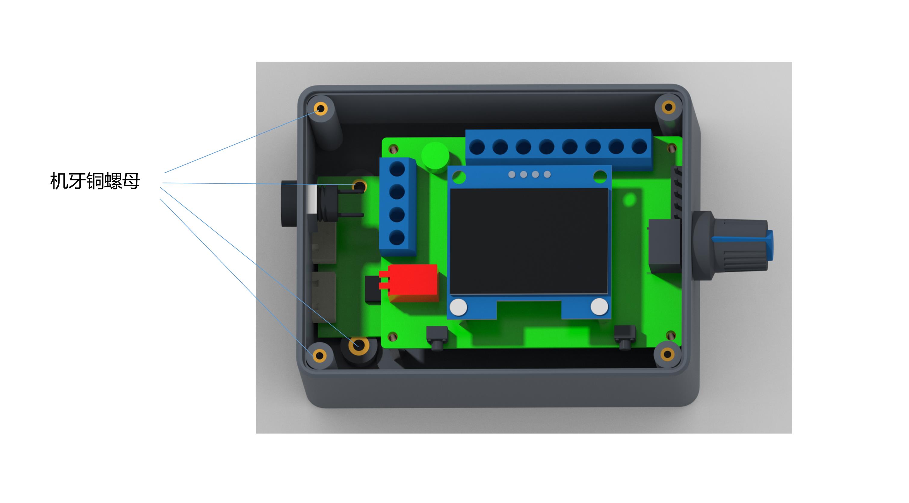
In the configuration layout, the FG/FG*3 pin sets the feedback multiple. Add the jumper cap for 3 times FG, and remove it for single times FG.
Main Screen Display
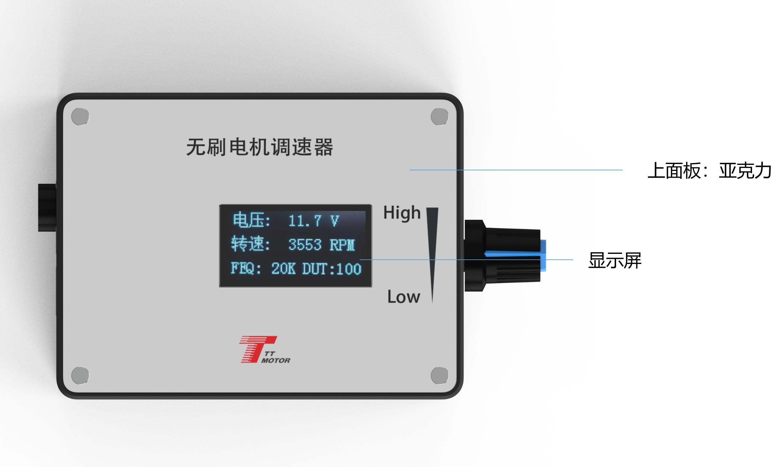
The main screen displays four key metrics: Input Voltage, Speed, Frequency, and Duty Cycle. To display speed correctly, the FG/FG*3 and pole number must be configured properly.
(1)
The positive and negative power supply of the governor must be connected correctly according to the instructions. Do not reverse the connections, otherwise the governor will not work and may burn out.
(2)
The governor is designed specifically to match motors that utilize the control interfaces specified above.
(3)
The five ports numbered 5 to 9 must not be accessed with voltages exceeding 5V.
Q1: What is the input voltage and current limit for this governor?
A1: The working voltage range is DC 5V to 28V, and the rated current is MAX 2A. If you need to control a motor with a higher current draw, connect the motor's power line directly to the power source rather than routing it through the governor.
Q2: How do I change the PWM frequency settings on the driver board?
A2: Press and hold touch switch 1 before powering on the board. Power up the board and release the switch when the screen displays "FEQ:20K". You can then use touch switch 1 to decrease the frequency or touch switch 2 to increase it. The default setting is 20KHz.
Q3: What is the maximum voltage allowed on the signal ports (ports 5 to 9)?
A3: The input voltage on these five ports (5, 6, 7, 8, 9) must not exceed 5V. Exceeding this voltage limit may cause damage to the board.
Q4: How do I configure the motor feedback signal (FG/FG*3)?
A4: The feedback multiplier is set via the FG/FG*3 jumper pins. Adding a jumper cap configures the feedback to 3 times FG (FG*3), while leaving the jumper cap off configures it to single times FG.
Q5: How can I change the initial direction state (CW/CCW) of the motor?
A5: The initial direction when the control line is suspended is set using the CW/CCW jumper pins. If you add the jumper cap, the default direction is CCW. Without the jumper cap, the default direction is CW.
Q6: What happens if I reverse the positive and negative power supply lines?
A6: Reversing the positive and negative power inputs will prevent the governor from operating and will likely damage or burn the board. Always double-check your connections before powering on.
 Zentec Motor