1 / 5
 Zentec Motor
DC 5V - 28V
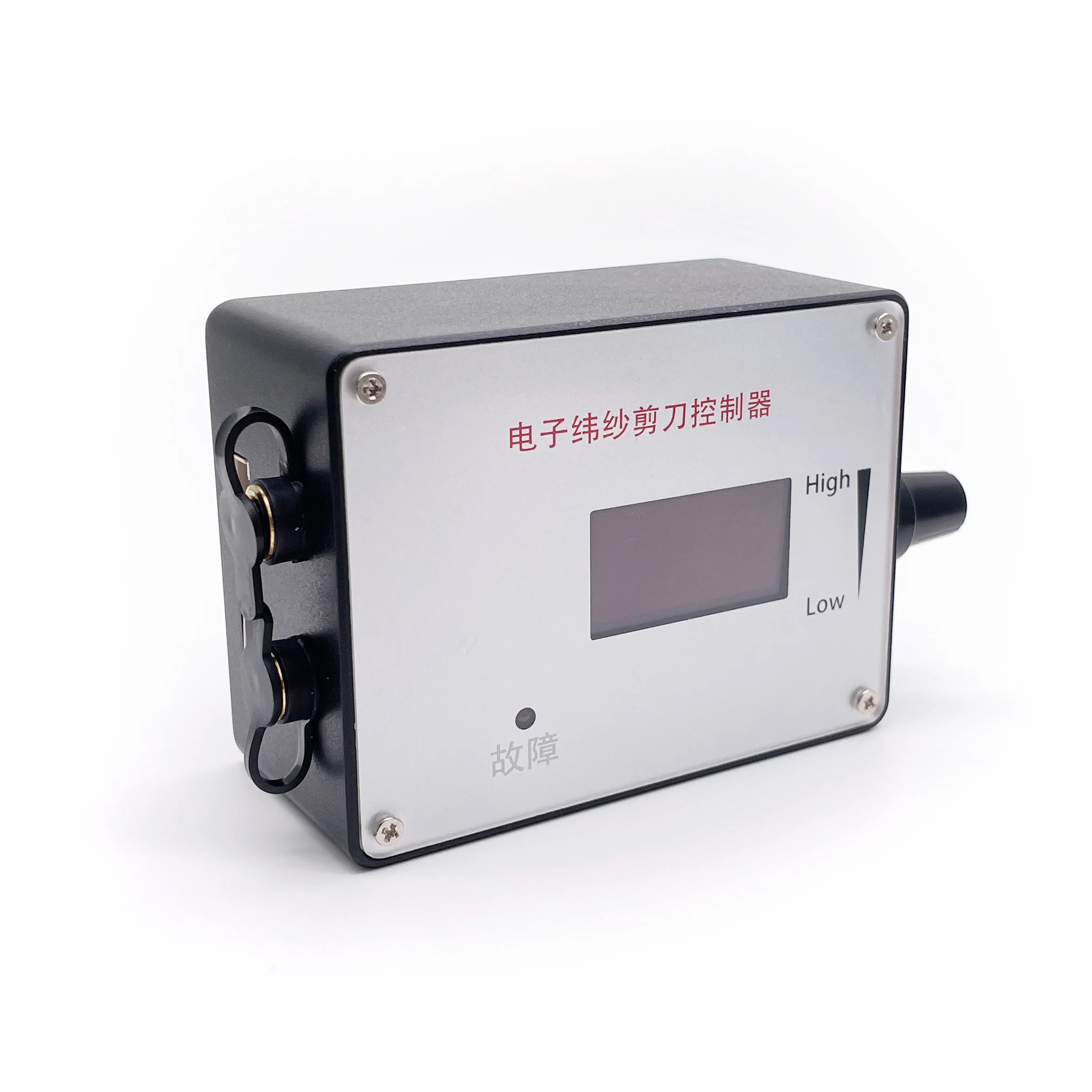
MAX 2A. To control the motor with greater current, the motor power line is directly connected to the power supply, bypassing the governor.
0 ~ 100KHz
0 - 5V
Working: -10°C to 70°C
Storage: -30°C to 125°C
Length 60mm X Width 40mm
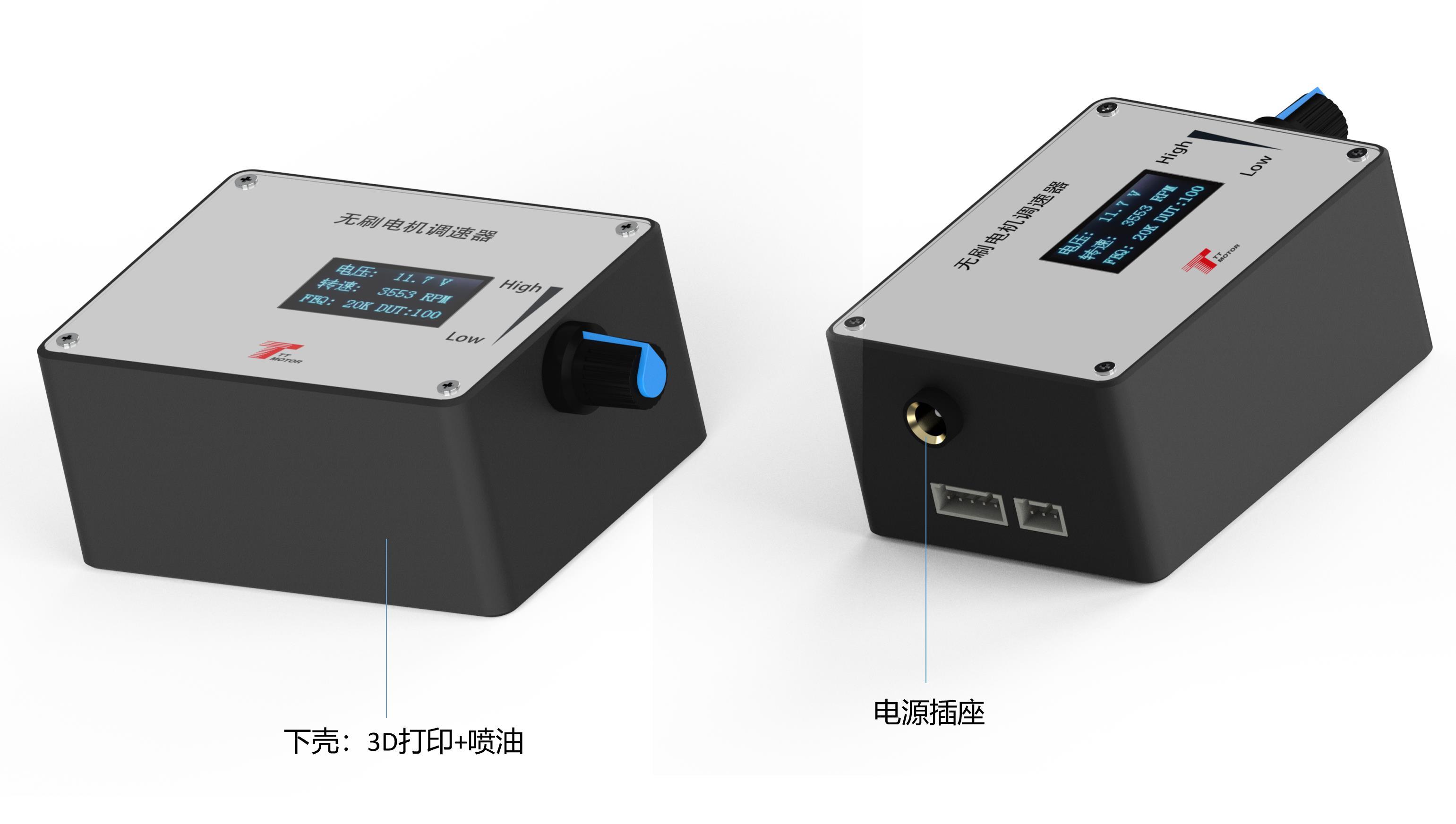
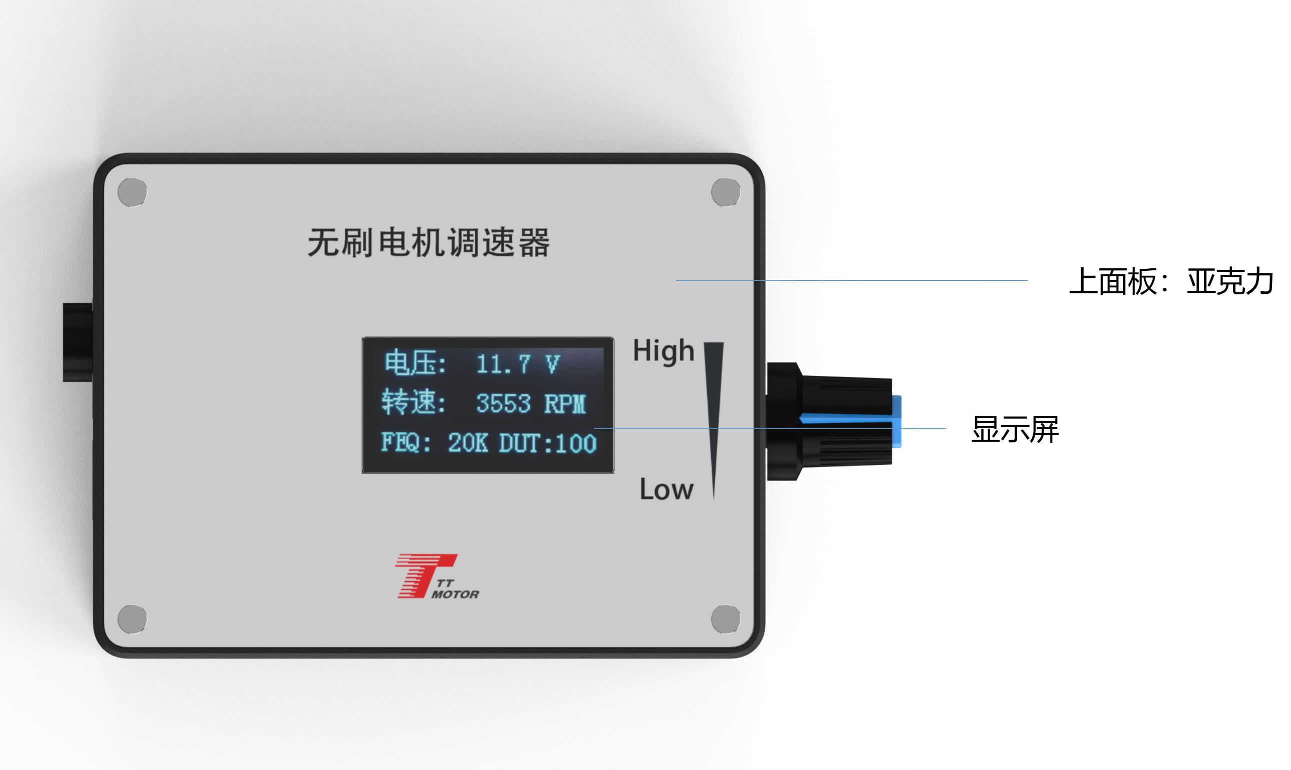
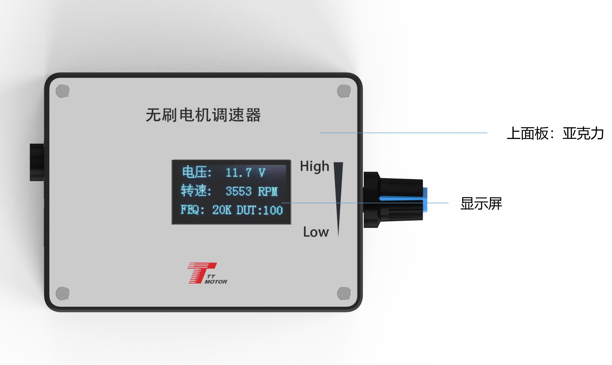
Press and hold touch switch 1 before powering on. Connect power to the governor board, wait until the screen displays "FEQ:20K", and then release the button. Touch switch 1 to decrease and touch switch 2 to increase. The factory default frequency is 20KHz.
Before powering on, press and hold both touch switch 1 and touch switch 2. Power on the governor board, wait until the screen displays the polarity selection message, and release the buttons. Touch switch 1 to decrease and touch switch 2 to increase. Configure to match the motor design. Factory default is 1 pole.
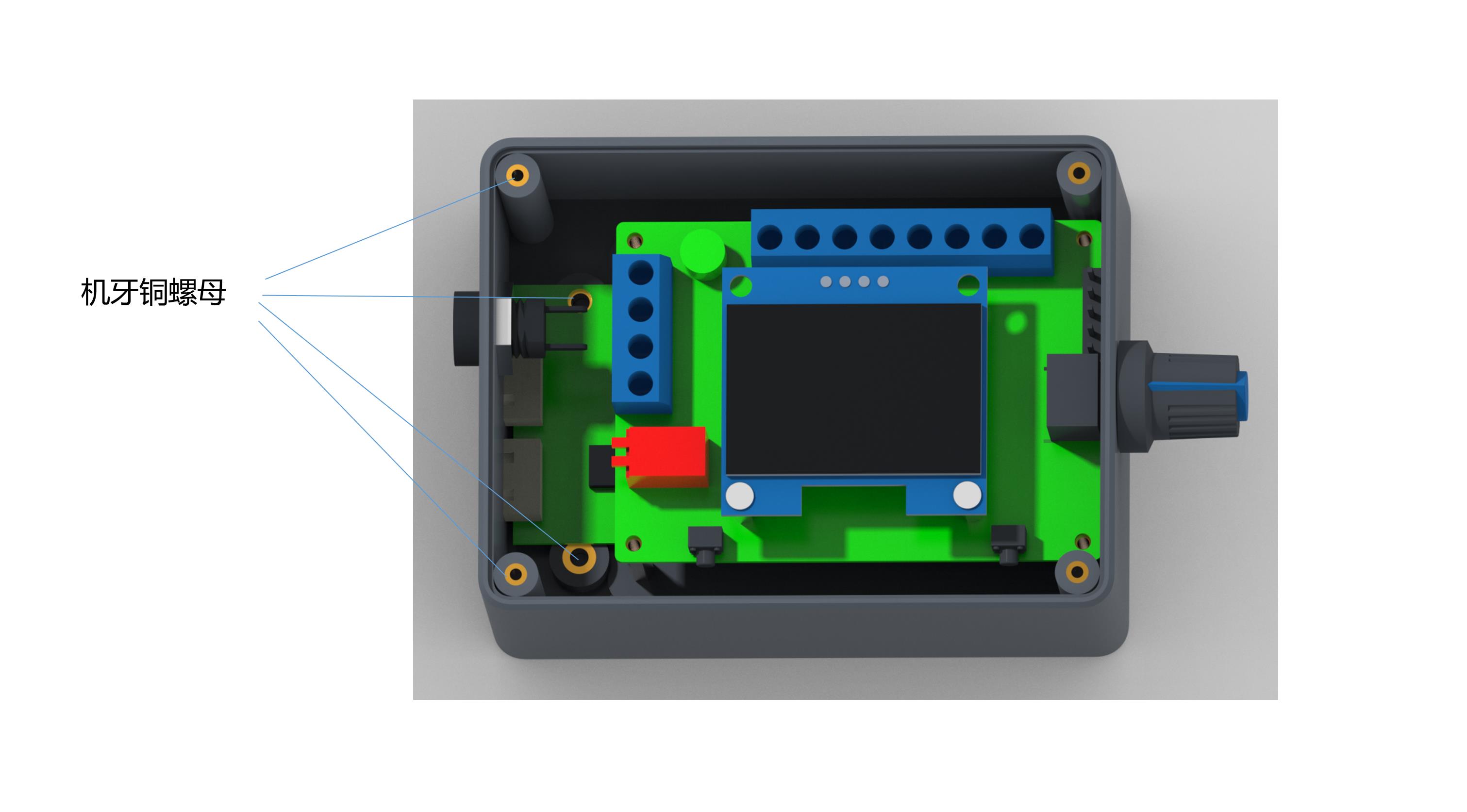
Set the feedback multiple using the FG/FG*3 pin. Configure based on whether the motor's feedback is single FG or 3 times FG. Adding the jumper cap sets it to 3 times FG; removing it sets it to single FG.
Set the initial state direction using the CW/CCW pin. Determine this based on whether the motor runs CW or CCW when the direction control line is suspended. Add a skip cap for CCW; leave it off for CW.
Q1: What is the input voltage and maximum rated current for this governor?
A: The voltage range is DC 5V-28V, and the maximum rated current is 2A. If you need to control a motor requiring a higher current, connect the motor's power line directly to your power source rather than routing it through the governor.
Q2: How do I change the frequency settings of the driver board?
A: Press and hold touch switch 1 before powering on the board. Once you power on the board, wait for the screen to show "FEQ:20K", then release the switch. You can then use touch switch 1 to decrease the value and touch switch 2 to increase it to your target frequency (factory default is 20KHz).
Q3: How do I configure the number of poles for my motor?
A: Before powering on, press and hold both touch switches 1 and 2. Power on the governor board, and when the screen displays the number of poles, release the buttons. Use touch switch 1 to decrease and touch switch 2 to increase the pole number to match your motor's design specification (factory default is 1 pole).
Q4: What is the function of the FG/FG*3 jumper cap?
A: It adjusts the motor feedback signal multiplier. If you do not install a jumper cap on the FG/FG*3 pin, the governor reads a single feedback value (FG). Adding a jumper cap configures the board to read 3 times the feedback (FG*3).
Q5: How is the initial direction of rotation configured?
A: The initial direction is set using the CW/CCW pin. If the motor's direction control line is left suspended, adding a skip cap sets the motor to CCW (Counter-Clockwise) mode, while removing the skip cap sets the initial direction to CW (Clockwise).
Q6: What is the maximum voltage allowable on the control ports?
A: The control interfaces (ports 5 through 9) are low-voltage signal lines. You must never connect an external voltage exceeding 5V to any of these five ports, or you risk damaging the controller.